Temperature Control
Whatever the process or the parameter (temperature, flow, speed for example), the principles of control are similar. Input and output signals are specified as appropriate to the application, usually analogue (e.g. thermocouple signal input, solid state output power control) but these may be digital.
This chapter assumes temperature control with either a thermocouple or platinum resistance thermometer input and a proportional control output.
Control of a process is achieved by means of a closed loop circuit (power fed to the heater is regulated according to feedback obtained via the thermocouple) as opposed to an open loop in the case of measurement only:
Temperature Measurement (Open Loop)
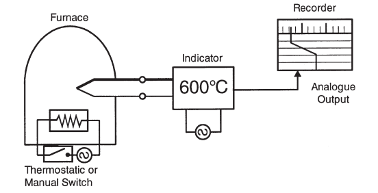
Fig 50: Temperature Measurement (Open Loop)
Temperature Control (Closed Loop)
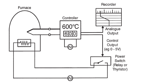
Fig 51: Temperature Control (Closed Loop)
With few exceptions, only very crude control of temperature can be achieved by causing heater power to be simply switched on and off according to an under or over temperature condition respectively. Ultimately, the heater power will be regulated to achieve a desired system temperature but refinement can be employed to enhance the control accuracy.
Such refinement is available in the form of proportional (P), integral (I), and derivative (D) functions applied to the control loop. These functions, referred to as control “terms” can be used in combination according to system requirements. The desired temperature is usually referred to as the “set-point” (SP) and the measured temperature is usually called the “process variable” (PV).
To achieve optimum temperature control whether using on-off, P,PD or PID techniques, ensure that:
a) Adequate heater power is available (ideally control will be achieved with 50% power applied!)
b) The temperature sensor, be it thermocouple or PRT, is located within reasonable “thermal” distance of the heaters such that it will respond to changes in heater temperature but will be representative of the load temperature (the “thing” being heated).
c) Adequate “thermal mass” in the system to minimise its sensitivity to varying load or ambient conditions.
d) Good thermal transfer between heaters and load.
e) The controller temperature range and sensor type are suitable – try to choose a range that results in a mid-scale set-point.
Control Functions Simply Described
a) On – Off – Usually simplest and cheapest but control may be oscillatory. Best confined to alarm functions only or when “thermostatic” type control is all that is required, but this may be the most suitable means of control in some applications.
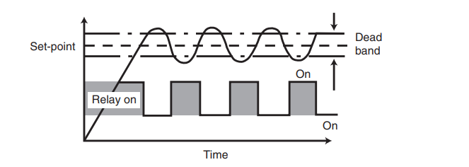
Fig 52: On/Off Control with Dead-Band
b) Proportional (P) – A form of anticipatory action which slows the temperature rise when approaching set-point. Variations are more smoothly corrected but an offset will occur (between set and achieved temperatures) as conditions vary.
Average heater power over a period of time is regulated and applied power is proportional to the error between sensor temperature and set-point (usually by time proportioning relay switching). The region over which power is thus varied is called the Proportional Band (PB) it is usually defined as a percentage of full scale.
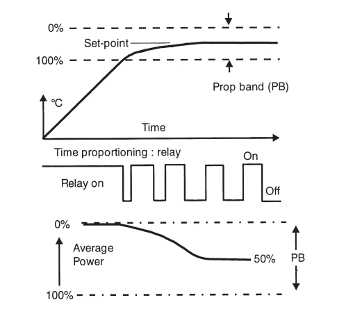
Fig 53: Proportional Control
c) Integral (Offset) I is the deviation of the sensor temperature from the desired value (set-point). This can be adjusted out manually by means of a potentiometer adjustment (Manual Reset) or automatically (Integral Action).
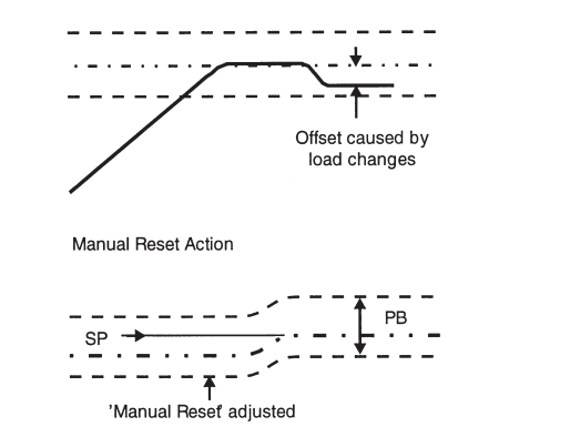
Fig 54: Offset
d) Proportional + Derivative (PD) – The Derivative term when combined with proportional action improves control by sensing changes and correcting for them quickly. The proportional action is effectively intensified (its gain is increased) to achieve a quicker response.
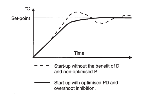
Fig 55: Start-up Performance with PD Control
PD action is commonly employed in general applications. Its use can minimise or even eliminate overshoot on system start up.
e) Proportional + Integral + Derivative (PID)
Adding an integral term to PD control can provide automatic and continuous elimination of any offset. Integral action operates in the steady state condition by shifting the Proportional Band upscale or downscale until the system temperature and set-point coincide.
f) Approach Optimisation
Under certain conditions, even with PID action, when the process is started, the set-point value can be exceeded prior to the process settling down and this is referred to as “start-up overshoot”. Many controllers employ certain techniques to minimize this situation; this is referred to as “approach optimization”
g) Choosing P, PD or PID
Although superior control can be achieved in many cases with PID control action,
values of the PID terms inappropriate to the application can cause problems.
If an adequately powered system with good thermal response exists and the best possible control accuracy is required, full PID control is recommended.
If somewhat less critical precision is demanded, the simpler PD action will suffice and will suit a broad range of applications.
If simple control is all that is required, for instance to improve upon thermostatic switching, Proportional (P) or on-off action will suffice.
If the controller specified offers adjustable PID values, the opportunity exists to optimise or “tune” the control loop to achieve the best possible accuracy in each case.
Fuzzy logic is a development of computer intelligence which, when utilized in controllers allows them to handle a diverse range of system demands. Basically, the controller benefits from optimization techniques which learn the process characteristics.
Benefits include a more rapid start up with little or no overshoot, more rapid settling following process disturbances (e.g. opening an oven door) and changes in set-point.
Controllers which are used in processes requiring both heating and cooling use a
heat-cool algorithm to achieve a stable temperature in the “cross-over region”
(a heating-cooling overlap). Such applications include exothermic conditions where
resultant work (process generated) heat could result in excessive temperature
(e.g. plastics extruder barrels).
Typically, the heating would be electrical and the cooling achieved by water or fan.
OPTIMISING CONTROL TERMS (TUNING)
The majority of modern controller and control systems utilize self-tuning circuitry for automatic loop optimization. Where manually adjusted PID values are used the “Fast Tune” guide below is useful.
All processes have some finite delays and on-off control will result in start-up temperature overshoot as shown.
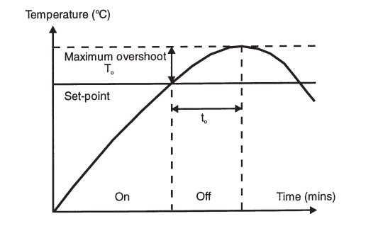
Fig 56: Start-up Temperature Overshoot
Firstly adjust P to minimum, D to off and I to off (or some very large value if not to off).
Full power is applied to the heaters and is switched off when the measured temperature rises to set-point. The resultant overshoot To and the time taken to attain the maximum overshoot to, allow suitable P, I and D values to be calculated:
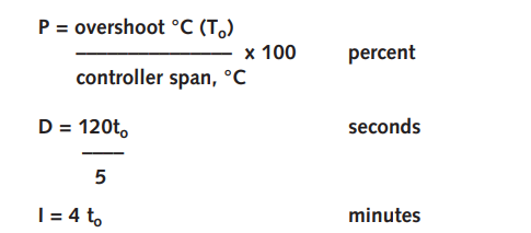
These or similar values should then be set on the controller and good results will be achieved.
For critical processes there are alternative more precise methods for obtaining optimum PID values. Such methods are more time consuming and Auto Tune Techniques described below provide an attractive solution in most applications, simple or complex.
Auto tune controllers utilize PID terms and an “approach” feature which are all optimized automatically. During the first process warm-up the controller familiarizes itself with the system dynamics and performs self-optimisation. No user adjustments are required for PID values. Some instruments include an “approach” feature to minimize or eliminate start-up overshoot, also automatically.
Accurate and reliable energy regulation are essential for good control loop performance if it is assumed that suitable PID values have been determined and applied.
Depending on the method of applying energy to the process, for example electrical energy to a resistive heating element, a suitable type of controller output arrangement must be specified. In some cases, more than one output may be required (e.g. for multi-zone heaters, heating-cooling applications).
Options most commonly available are:
Electromagnetic Relay, typically rated 2,5 or 10 Ampere contact. Electronic relay (Solid State Relay or SSR) typically rated up to 3kW. Thyristor Unit, usually rated from 3kW to 100kW.
Analogue dc control signals, usually 0-1V, 1-5V, 4-20mA and similar to operate external energy regulation devices or converters (e.g. external thyristor units).
Valve Positioner, actuator drive for gas or oil fired burners with or without position feedback function.
Whilst built-in alarms provide a convenient method of “policing” the process against over or under temperature occurrence, they should never be relied upon for plant safety. If there is any possibility that component or sensor failure could result in heating power being permanently applied instead of regulated then a completely independent over-temperature alarm should be utilized. In the event of excessive temperature rise, such an alarm would remove energy from the process.
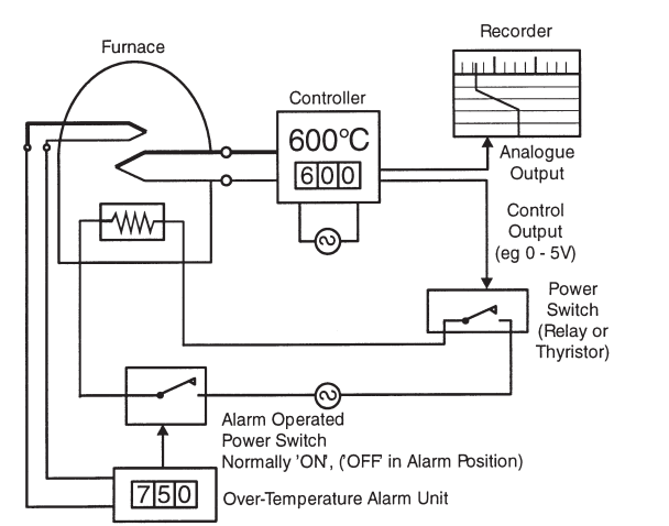
Fig 57: Temperature Control System with Independent Alarm
1. High Alarm – this operates if the process temperature exceeds the alarm set value.
2. Low Alarm – this operates if the process temperature falls below the alarm set value
3. High / Low Alarm – this operates if the process temperature exceeds or falls below the alarm set values.
4. Deviation Alarm – this operates if the process temperature reaches a pre¬determined deviation from the set-point.
5. Process Alarm – this operates if the process temperature reaches the alarm set value, regardless of the process set-point value.
In practice, various features are available with alarm functions to suit process needs. These include dead-band, delay and reset functions and alternative contact modes.
Can’t find what you need? Call or email our technical sales team on
+44 (0) 1243 871 280 or sales@labfacility.com for help with product selection and technical support